
Get in touch with LFADJ Company

Updated October 2026
Pneumatic telescopic lighting masts are supports composed of nested tubes that, when pressurized with air, extend to support a lighting head. First match the mast to the complete head, the operating height and the approved base, and then plan the air supply, controls and safe lowering.
Selection at a glance
- Elevation: compressed air extends the mast; holding arrangements differ between designs.
- Head fit: Assess the load in the head (lamps, brackets, cable, cameras, and other equipment)
- Site fit: ground, mounting, weather and overhead hazards belong to the installation plan.
- Supply scope: separate a mast assembly from a complete powered lighting tower.
A taller mast can lift a lamp over nearby obstructions; however, the arrangement of the head and support has to work in conjunction. A wide replacement light bar changes wind loading. A vehicle roof provides a structural connection. A rental return adds lowering and transport tasks after the night shift.
When assessing pneumatic telescopic lighting masts and telescopic lighting tower options, examine the lifting mechanism first, then narrow the choice by the support and head conditions and the work required to provide a usable installation.
What is a pneumatic telescopic lighting mast?
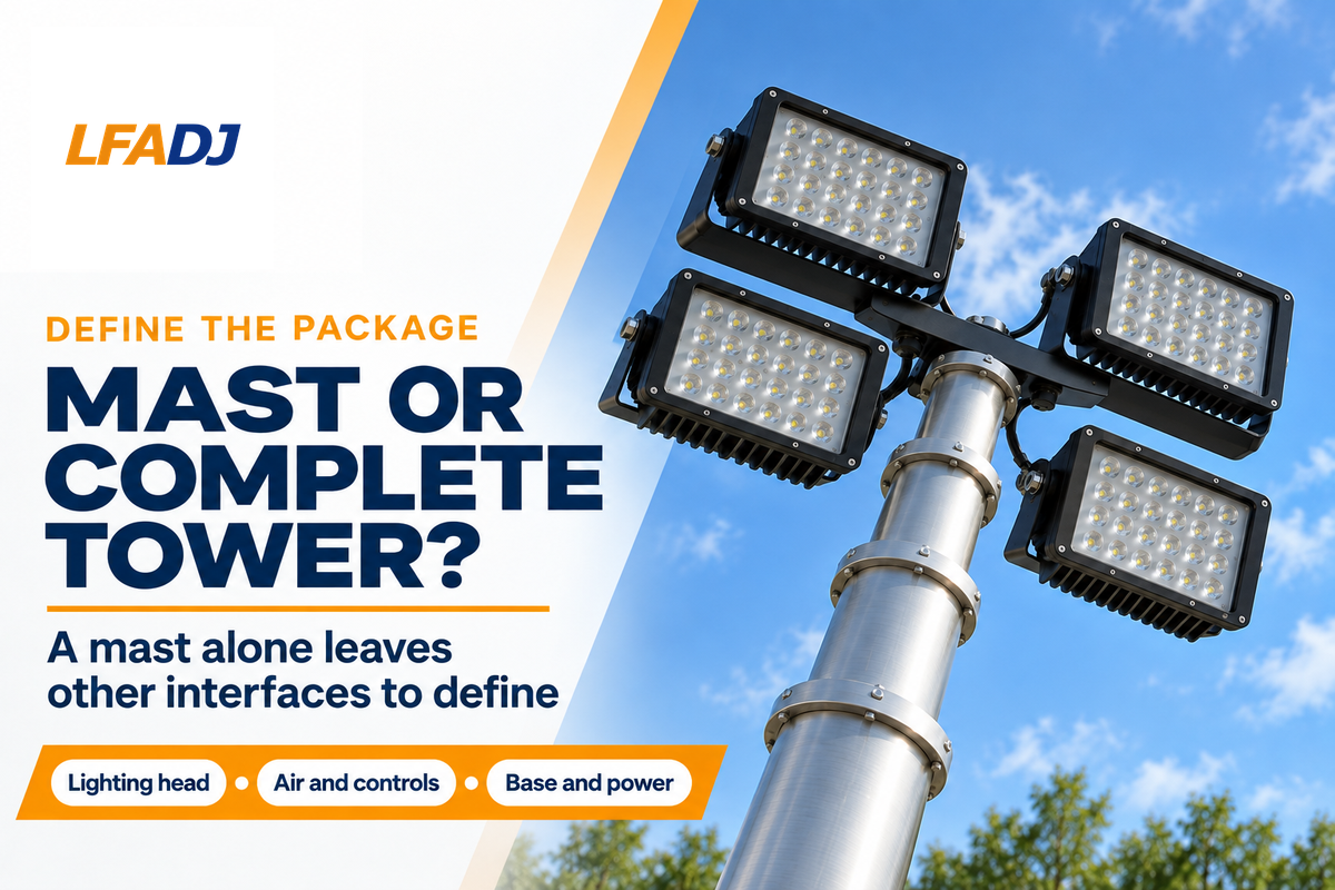
A pneumatic telescopic lighting mast is an extendable support with air pressure. The lamp is supported at the top, while the base connects to a vehicle, trailer, or another approved support. The mast system may contain cabling, controls and an air supply, as configured.
The sections telescope into one another for transport and storage. Extended height describes the extended position; retracted height describes the nested position. Both affect purchase; the first pertains to the position of the lighting equipment, and the second to vehicle packaging, clearance, transport and storage.
Telescopic pneumatic masts are designed to raise and support the lighting head. A pneumatic light mast is just one element of a complete light tower system; a complete light tower system may include a generator, a fuel system, a stabilizer, and a trailer chassis. Buying the mast alone leaves the head, utilities, and the balance of the installation to be defined. A historical vehicle-mounted lighting example appears in the Will-Burt pneumatic mast patent; it describes a particular design.
Lighting masts and communications masts share some mechanical ideas, but their payloads create different demands. A directional radio antenna, a sensor and a broad floodlight head have different shapes and mounting interfaces. For a combined head, everything must be in the same load and cable-routing assessment.
How air pressure raises, holds and lowers the mast
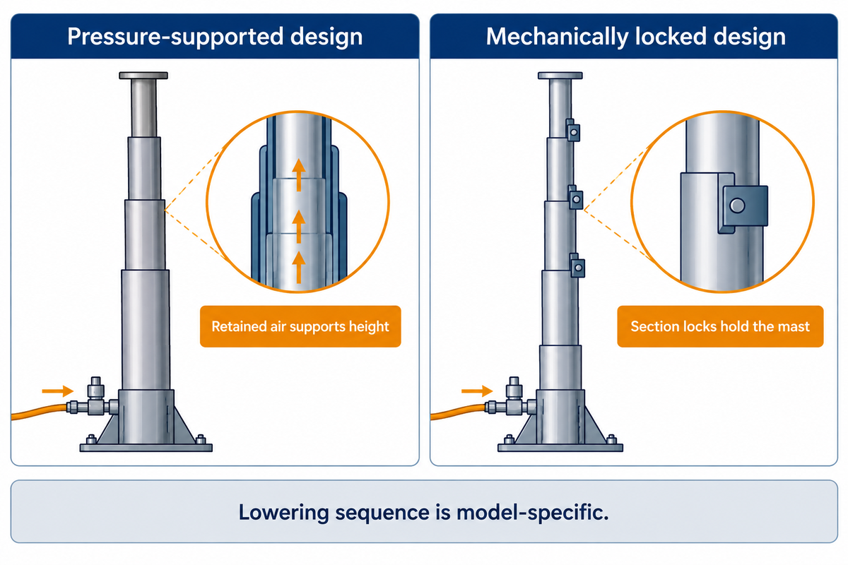
A pneumatic telescoping mast has an internal pressure system that extends its nested sections. Some designs maintain air pressure, while lockable designs use mechanical locking arrangements. Controlled exhaust and lock release enable the mast to lower in the design’s intended sequence, with support and installed head conditions taken into account.
The action of extending the mast is similar to extending a telescope, but the mast is loaded and maintains pressure. A compressor is the air source for many of the installations. Some mast families can use a hand pump, including versions with an integral hand pump. The air delivery and controls for the mast depend on the selected mast model, not the word pneumatic.
In a pressure-supported arrangement, retained air is part of the holding system. Retained pressure and compressor duty describe different characteristics: one is concerned with air in the mast; the other with the characteristics of the pump during its operating cycle. A mechanically locked mast adds a load-holding mechanism at its section collars. The collar release, pressure support and lowering controls must function in the sequence intended.
Different responses to power loss, air loss and a stop command exist. The Will-Burt US8237306B2 control system patent describes a valve and retraction arrangement. That sequence is part of the described design. Upon equipment transfer, operating instructions supplied with the equipment should specify the system responses to interruptions.
Prior to field deployment, an operator should know labelled functions to raise, lower, stop and stow that equipment. Improvisation of collar-release procedures, bypassing of interlocks and improvised venting of pressure are hazardous servicing and control practices and don’t help to accomplish deployment tasks.
Height, payload and wind: choose a compatible mast
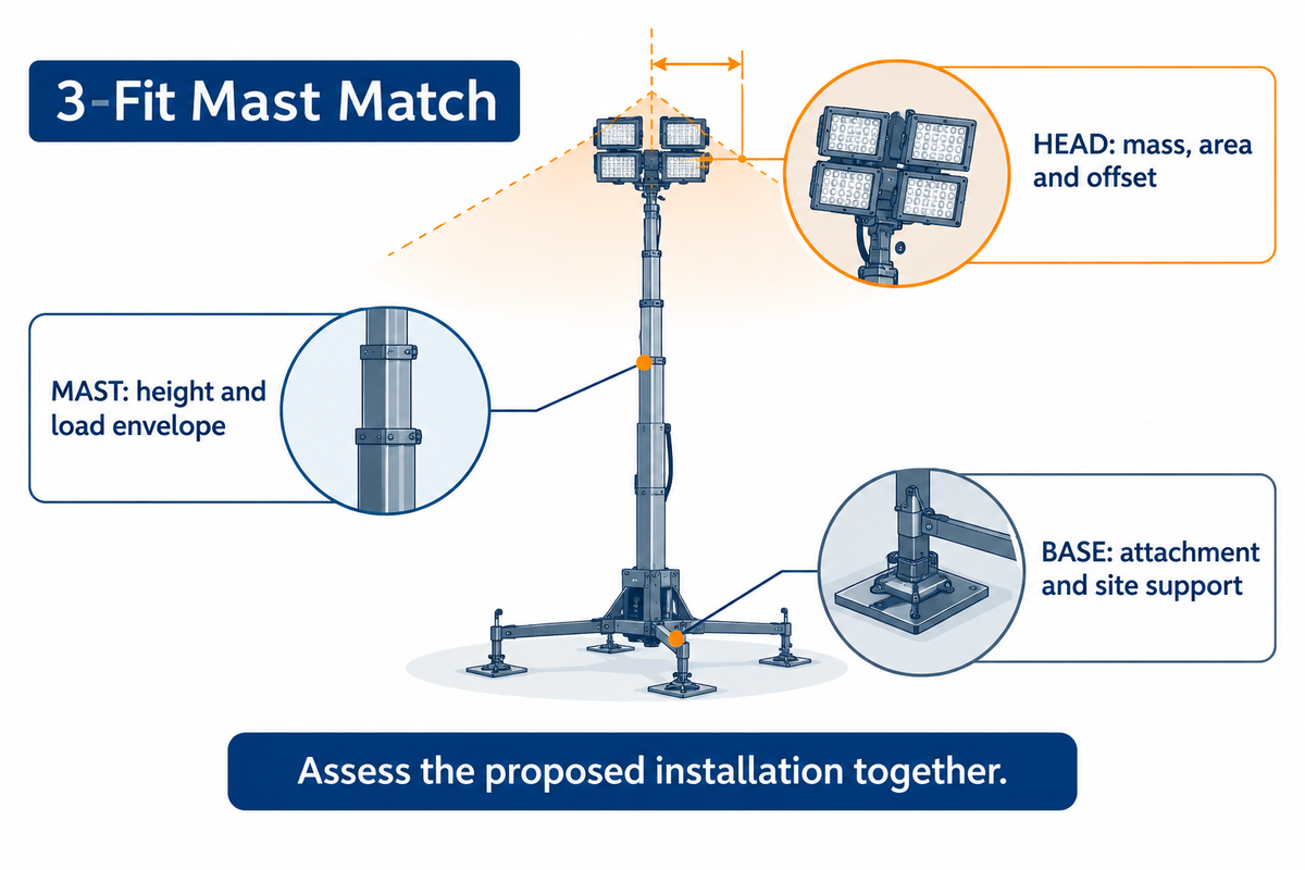
Choose a lighting mast whose working envelope and approved support arrangement suit the complete head. Loads, winds, and other weather conditions affect the limits of a supporting structure and thus the height at which the mast can be installed. Advertised height limits of a mast are based on a number of factors.
3-Fit Mast Match
The 3-Fit Mast Match screens the lighting head, mast and base together before a configuration is selected.
| Fit | Input to record | Decision it changes |
|---|---|---|
| Head: mass | Total fitted head mass, including brackets, cable and accessories | Use the payload allowance for the intended operating configuration. |
| Head: wind area | Head dimensions, orientation and projected area | Evaluate the chosen head shape against the approved wind/load basis. |
| Head: offset | Center-of-gravity position and mounting offset | Keep the top adapter and off-axis loading within the approved arrangement. |
| Mast: height | Working height and retracted height | Resolve lighting position and transport packaging together. |
| Mast: load envelope | Exact model, headloads and support conditions | Keep a family maximum separate from the selected model’s rating. |
| Mast: air and holding | Air supply, holding method and lowering controls | Choose compatible utilities and a defined interruption response. |
| Base: attachment | Mounting drawing and approved load path | Assign roof, chassis or foundation work to the responsible integrator. |
| Base: site | Ground strength, slope, stabilization and wind arrangements | Select an outdoor installation that suits the actual site. |
| Base: movement | Raise, retract, stow and transport envelopes | Plan the whole movement path, including takedown. |
NASA’s drag explanation references air density and velocity squared and relates aerodynamic force to a reference area and a drag coefficient. Head mass and wind area pertain to different issues. A lightweight panel can present a wide wind area.
Example: a maintenance team plans to replace a compact head with a wider lamp bar on an existing trailer. For a simplified comparison, hold the head geometry, drag coefficient and air density constant, and compare wind speeds of 5 m/s and 10 m/s. The speed doubles; the velocity-squared term gives (10 ÷ 5)² = 4 times the drag. This compares aerodynamic loading under stated assumptions, not a permitted operating wind speed. Changing the head shape introduces another variable. The team keeps the replacement head out of service until its mass, area, offset and base arrangement have been assessed against the selected mast’s documented envelope.
How much weight can a telescopic mast carry?
There isn’t a payload capacity for all telescopic masts; use the exact model’s rating at the intended height and support conditions. Include the entire assembled and mounted mass in that evaluation, rather than the lamps alone. A cable weight, pan-and-tilt unit and a camera can consume part of the headload before another lamp is added.
Stability of a light assembly is a combination of all elements, including the support and base. The UK Health and Safety Executive’s guidance on outdoor equipment supporting lights addresses overturning, mast buckling, ground conditions, slopes, and weather. An approved base arrangement should be unaltered. The addition of guy wires or other ballasting alters the assessed support arrangement.
Pneumatic, winch or hydraulic: compare the trade-offs
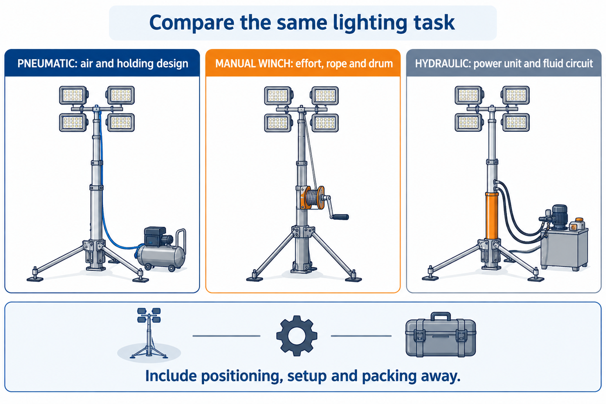
Compare various types of telescopic masts against the same lighting task, head, and support conditions. Direct pneumatic elevation needs a proper compressed-air system; a manual cable winch needs operating effort and care with rope and drum; a hydraulic lifting arrangement requires a power unit and a fluid circuit and has its own servicing requirements.
Here, “winch” means a hand-operated cable winch. Winches are mechanisms and can be powered. In the American Society of Mechanical Engineers’ public description of winches, units powered by electricity, engines, compressed air, or hydraulics are addressed. Thus, naming the drive and lifting mechanism avoids comparing overlapping categories.
| Arrangement | Planning emphasis | Useful buying question |
|---|---|---|
| Direct pneumatic mast | Air delivery, section condition, holding design and controls | Does the complete air-and-control package suit the intended duty? |
| Manual cable winch | Operator effort, access, rope/drum inspection and holding mechanism | Can the assigned team perform the complete setup and packing-away tasks? |
| Hydraulic lifting arrangement | Power-unit integration, fluid circuit and qualified maintenance | Does the supplied lifting assembly meet the same head and site requirements? |
Manual lifting can suit a job where powered utilities add unwanted complexity. A powered arrangement can greatly reduce the effort of elevation while positioning, stabilizing and inspecting remain. A supervised full deployment demonstration should cover the complete task, rather than an isolated extension-time demonstration.
For manual elevation, review the manual winch tower page at LFADJ as a separate route. Prospective buyers considering a motor-driven arrangement can compare electric mast towers. Electric drive should be distinguished from a hydraulic lifting circuit.
Mounting and cable routing need their own checks
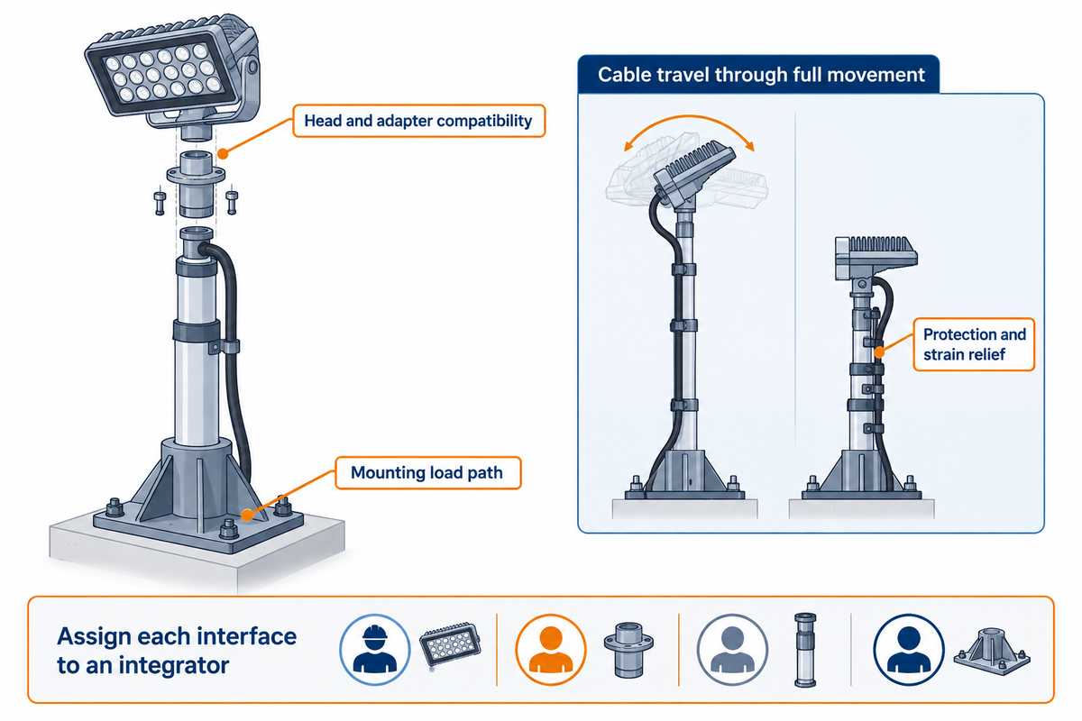
Mounting and cable routing can rule out an otherwise attractive mast. The base must transfer its loads into an approved support and the top adapter must be compatible with the head. Power and control cables must have an intended route through extension, rotation and retraction, with the required travel, protection and strain relief.
A vehicle roof, a trailer chassis and a portable tripod are all different supports. Mounting options should identify the appropriate attachment and operating arrangement. Base tube diameter is a packaging dimension. The roof structure and fasteners carry the loads of the system. Mast accessories also enter into the head-mass and transport-space assessment. For outdoor supports, UK guidance from HSE addresses foreseeable wind loading, ground strength and slope; this does not approve a particular vehicle installation.
| Interface | Typical project bottleneck | Responsible handoff |
|---|---|---|
| Head to top adapter | Bracket pattern or offset differs from the selected head | Head supplier and mast integrator: approved assembly drawing |
| Head to wind envelope | A wider light bar changes the exposed geometry | Mast integrator: head-specific loading assessment |
| Base to vehicle | Mounting location lacks an approved load path | Vehicle bodybuilder: structural installation detail |
| Base to ground | Site slope or ground support differs from the installation basis | Site manager: placement and stabilization plan |
| Air supply to mast | Pressure specification is given without the needed air delivery | Air-system supplier: compatible delivery and controls |
| Cable to moving sections | Available cable travel differs from the required mast movement | Electrical integrator: complete movement-path detail |
| Controls to positioning head | Supply or control interface differs between components | System integrator: interface and stop/stow description |
| Lighting to power supply | Only the lamps have been included in the electrical load schedule | Electrical integrator: complete operating and starting-load schedule |
| Stowed mast to transport | The nested head obstructs the intended transport position | Vehicle integrator and fleet operator: stow/transport handover |
Example: A fleet is considering a used antenna mast from a ham radio installation for use on a maintenance vehicle. The new head incorporates lights and PTZ cameras. The old cable carried a different electrical load. The mast can be extended, but the project still has unresolved top-adapters, cable and vehicle-mounted support. Procurement assigns the head drawing to the lighting supplier, the roof attachment to the bodybuilder, and the electrical/control interfaces to the electrical integrator. A single installer is then responsible for the complete movement-path. The fleet is taking an installation project approach, rather than buying a taller mast and leaving the interfaces to the end-user.
Plan deployment around the actual site
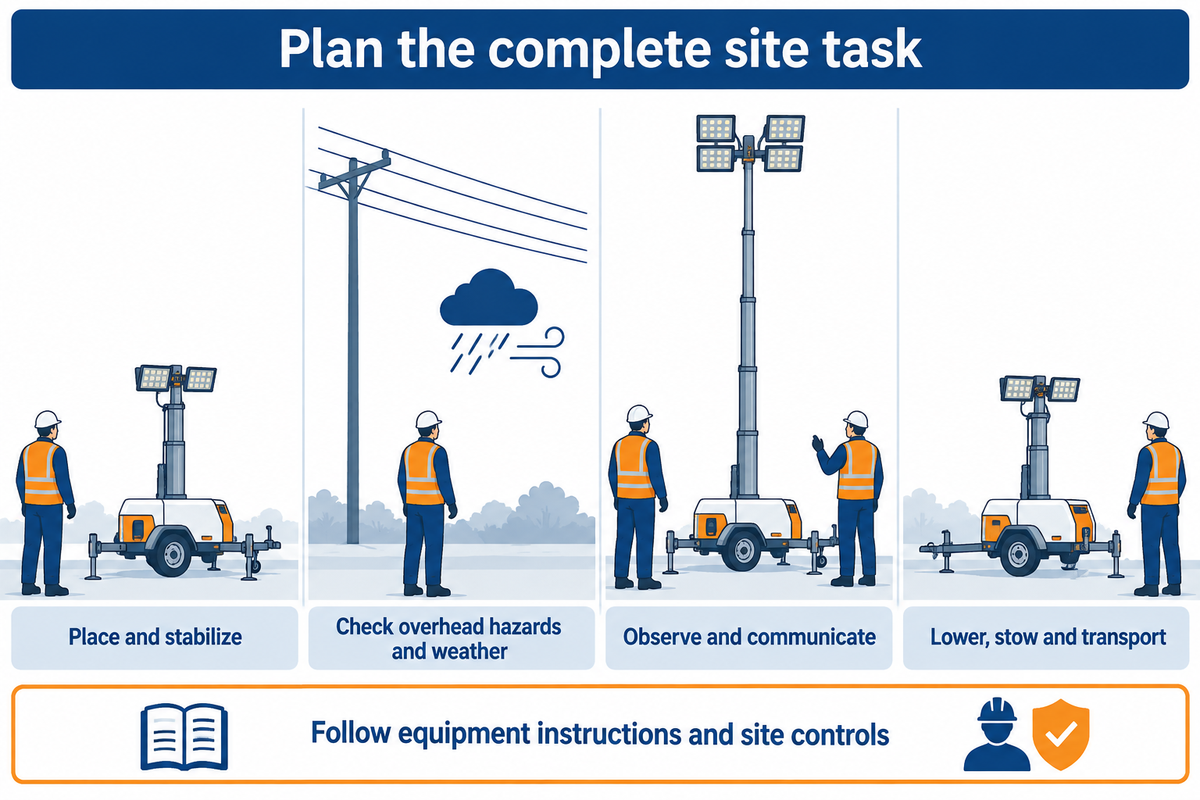
A deployment plan should cover placement, stabilization, lifting, use, lowering and transport. The equipment operating instructions define the sequence and limits of use. The site plan should incorporate overhead electrical hazards, ground conditions, and changing weather, as well as the people and means of communication required to carry out the task.
In US construction work, according to Occupational Safety and Health Administration rule 1926.416, employers must identify energized-circuit hazards before work and protect people from contact. Generally, the applicable rules and the arrangement of the site dictate the controls and clearances. A generic mast guide can’t dictate a single distance for different electrical conditions.
Takedown warrants its own briefing. The NY State Fatality Assessment and Control Evaluation report describes how a mobile light tower, during its removal, was involved in fatal contact with powerlines. The incident was not witnessed. The mast was apparently raised for an unknown reason. Various site-survey, training, possible control familiarity and lone working concerns were noted by the investigators. This was a mobile light tower incident, without an assumed pneumatic mechanism.
Can one person set up a telescopic mast?
One-person operation should be allowed only where the task can be completely performed by one person as laid down by the equipment instructions and site arrangement. Staffing should be sufficient for positioning, stabilization, managing and observing the moving head, operating the elevation control and safe takedown. Additional factors such as restricted visibility, traffic management, overhead hazards, and other controls/barriers may increase the need for observation and cooperation.
Example: A road-maintenance crew working at night finishes its shift with a light tower. An employee from a different work crew comes to pick up the equipment. The employee picking up the equipment observes how the controls work to raise and lower the tower. The employee also notices how the tower is stowed. The employee picking up the equipment points out to the collection team the overhead hazards and the agreed observation and communication arrangements for retraction and packing away. The equipment rental handover shows how the same equipment must be set up and then broken down, because the movements and positions are different. Emergency services can use the same planning distinction when the deployable mast has to be returned to transport configuration after an emergency response; a rapid deployment objective also requires controlled return.
Changing wind or ground conditions can alter the installation’s stability during use. Outdoor-equipment guidance includes local weather monitoring and a planned response to adverse conditions. In classified industrial areas, the electrical equipment must also suit the location: hazardous-location lighting requirements need a separate application assessment.
Maintenance, pressure loss and slow retraction
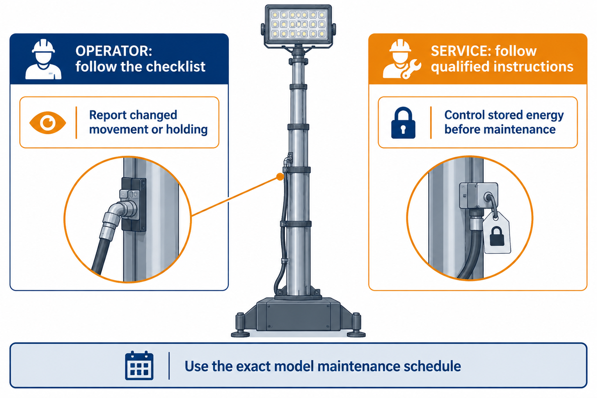
A work crew should follow the exact mast’s maintenance schedule and condition checks and address signs of failure before continued use. Evidence of failure may include dirty tube surfaces, damaged cables or hoses, erratic movements, and excessive noise. It may also be stuck and experience an unexpected loss of height. The work crew should follow qualified instructions to determine if equipment needs cleaning, lubrication, or seal work. Repairs to pressure systems also require different competencies and energy-control arrangements.
Certain models of factory-pre-lubricated pneumatic mast ranges, under normal operating conditions, use condition-based cleaning and lubrication. Harsh environmental conditions can affect maintenance requirements. Issuing blanket monthly lubrication instructions can result in the operator performing a maintenance task that isn’t required, just as a “maintenance-free” statement can conceal the need to inspect a working installation.
Routine observations should follow the operator’s checklist and include: tubes and surfaces, hoses and connections, cable, mounting, labels and the stowed arrangement. Changes in movement and holding behavior should be reported to the service team. Increasing pressure or forcing a sticking part isn’t a substitute for a fault assessment.
“Plant and equipment must be made safe before maintenance starts.”
HSE’s UK guidance is specific to isolation of electrical and other power supplies, release of stored energy and support of parts which could fall. Special conditions can be incorporated in service instructions. An operator checklist should identify the reporting and withdrawal steps; qualified service instructions should define the maintenance, repair and/or cleaning work to be performed.
Older equipment should have points of maintenance access and appropriate guarding. The positioning of a lubrication point, or a control that’s difficult to read, can affect who can perform maintenance on a mast and how the work area is protected. This should be taken into consideration when a mast is installed in a body or placed above a vehicle roof.
For persistent pressure loss, slow retraction or unanticipated movement of the apparatus the service handover should include the mast model, fitted head, observed symptom and operating conditions. Keep people clear of a suspected uncontrolled movement and follow the site’s isolation and emergency procedures if an electrical and/or mechanical hazard is present.
Compare installed scope before comparing mast prices
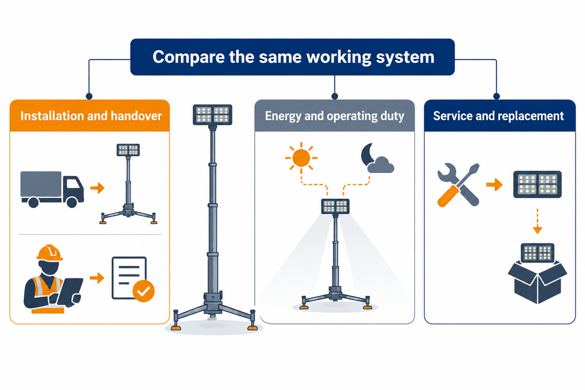
During a planned procurement, consider the scope required to put each mast in the same working service. A bare assembly, a mast with a head and a complete trailer tower leave different work to the buyer. Consider installation and ongoing ownership costs in addition to the quoted equipment, using the same assumptions concerning lighting task and operating conditions.
How much does a telescopic mast system cost?
There’s no single price for every telescopic mast system. Consider the equipment supplied and the remaining work to be done for installation. Head configuration, air supply, controls, mounting and commissioning can alter the total even if mast only prices appear to be the same. Consider the same usable system, and provide for its energy, service, and replacement during the ownership period.
The US Department of Energy’s Life-cycle cost training includes first cost, installation, operation, maintenance, repair, replacement and disposal. The method is useful for a finance review. The article’s Federal purchasing requirements have their own jurisdiction.
The scope of work is different when making a mast only enquiry compared to a complete lighting-tower enquiry. This example separates product-package items from the site work and integration.
| Scope type | Mast-only enquiry | Complete lighting-tower enquiry | Buyer action |
|---|---|---|---|
| Mast assembly | Specified mast and holding arrangement | Mast within the integrated package | Keep exact head and height requirements equivalent. |
| Lighting head | Separate head and adapter scope | Lighting configuration within the package | Itemize the lamp assembly and its mounting. |
| Electrical generation | Site or separately supplied power | Generator within the quoted package, if included | State the complete electrical load schedule. |
| Base and transport | Separate support or vehicle installation | Trailer-based package configuration | Separate transport supply from site suitability. |
| Air equipment | Air source and controls to be itemized | Air-system inclusion to be itemized | Name the air-system supplier and interface. |
| Cabling and controls | Integration work between components | Included functions and external connections | List the control and cable interfaces. |
| Installation | Mounting, wiring and handover work | Remaining site work and handover | Name who carries out each site task. |
| Service support | Component and installer responsibilities | Package and installation responsibilities | Set warranty, service and spare-parts scope in the agreement. |
| Operating cost | Air, power, inspection and service inputs | Fuel, air, inspection and package service inputs | Use the same duty period in the ownership comparison. |
Assign the supply list to procurement, site interfaces to the installation lead, and comparison periods and cost assumptions to finance. Emergency readiness, availability, operator familiarity and a service arrangement also influence the decision.
Keep the document request in one purchase package: exact-model operating and maintenance instructions, head-load and wind/support conditions, mounting and wiring information, included air/control package, and applicable model-specific test or conformity documents. Management system certificates describe the organization; check the stated scope of each product report or certificate.
Are you preparing a lighting-mast enquiry? Send LFADJ the intended head and working height. Support and operating environment are also required. Compare Pneumatic Telescopic Lighting Masts configurations for the product package and quotation scope.
Integrating the mast with lights, power and controls
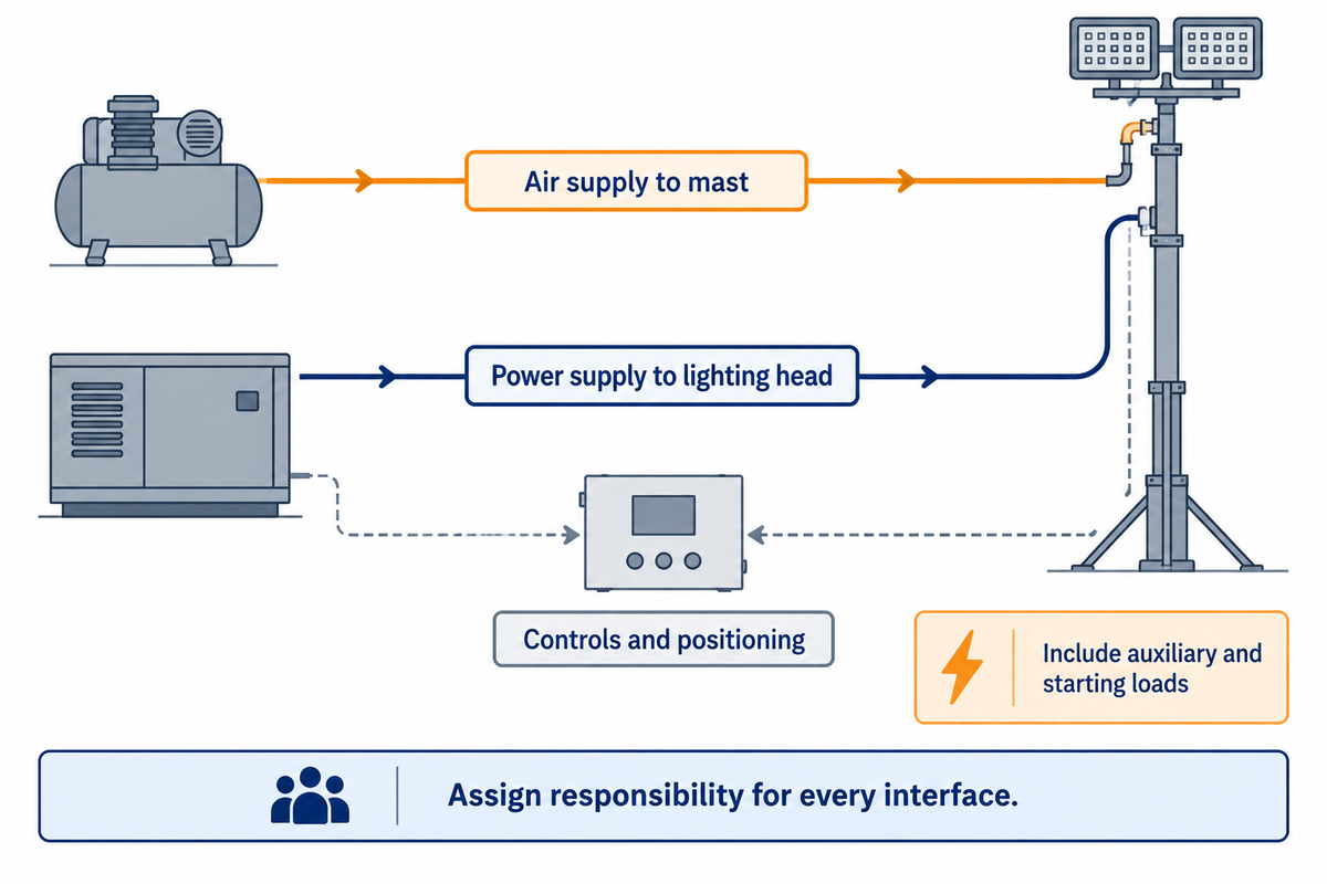
A lighting installation connects mast, head, power supply, air and control system in a defined arrangement. The lamp load and lifting controls may be on separate circuits. Determine who owns each equipment interface and how the assembled system raises, lowers, stops and returns the equipment to transport position.
Include positioning motors, compressor equipment and auxiliary loads in the electrical design where fitted. The starting behavior and supply requirements of those loads belong in the equipment’s load schedule. A generator-powered tower also has a fuel and engine-service scope. Review LFADJ’s power and engine-service configurations for that complete power-package choice.
Lighting documentation has its own version requirements. The International Electrotechnical Commission published the tenth edition of IEC 60598-1:2024, replacing the 2020 edition, for general luminaire safety requirements. For the latest edition, lighting documentation should identify the edition and the associated luminaire. However, in a current purchase, mast and mounting documentation identify their equipment and conditions.
For a lighting and camera installation, the power and control cable travel must accommodate the selected positioning head for the duration of the movement. The full-height positioning of the mast, a lower-height working position and the nested transport position may result in the cable being in a different location. The system handover should demonstrate the complete system and head mounted position in the required orientation.
Frequently asked questions
How high can a telescopic mast extend?
Choose the operating height for the complete head and base
The usable height is determined by the allowed head, mast and support arrangement. For product families that cover different extended and retracted dimensions, select the working position considering the lighting task and site envelope. A taller option may create added transport and support demands. Coordinate the exact model’s head and wind loads with its height.
What materials are telescopic masts made from?
Aluminium tube sections are common; composite options also exist
Aluminium sections are common in pneumatic mast ranges, and some manufacturers offer carbon fiber variants. An aluminum alloy designation and surface treatment are part of the model specification. Some manufacturers can anodize tube surfaces; anodised aluminium describes that treated material. Seals, section design and the environment also determine the supplied mast; therefore, material name alone isn’t a load rating.
Do I need guy wires with a telescopic mast?
Use the support arrangement specified for that installation
Guy wires are required where the approved installation requires guying; freestanding or supported arrangements depend on the mast model and approved installation. Factors to take into account include head geometry, height and wind loading, and the size and weight of the base. Use guy wire and anchor arrangement where applicable. Improper guys and ballast introduce loads that the support system wasn’t designed to support.
What is a telescopic mast used for?
Raising lights, communications equipment and other payloads
A telescopic mast raises equipment above its transport height and is commonly used to support lighting, telecommunications, cameras and sensors. A heavy duty pneumatic telescopic mast should be selected based on the fitted head and installation rather than a heavy duty label. Portable telescopic mast systems also require a suitable base and a defined transport arrangement.
How long does it take to deploy a telescopic mast?
Deployment time depends on the complete installation and site task
Deployment time should include positioning, stabilizing, inspection, utility connections and raising the equipment rather than just extending the tubes. A supplier’s demonstration should use the intended head, height, air supply and staffing. Record a supervised complete set up and a separate packing away demonstration during handover to show a practical staffing level for repeat work. You must not treat an extension time claim as the whole job.
References & Sources
- US8237306B2: Pneumatically telescoping mast having lighting and DC operated controls, original assignee Will-Burt; historical architecture context.
- Drag Equation, National Aeronautics and Space Administration, Glenn Research Center.
- Outdoor equipment to support speaker clusters, lights etc, UK Health and Safety Executive.
- B30.7: Winches, American Society of Mechanical Engineers, public description.
- 1926.416: General requirements, US Occupational Safety and Health Administration.
- Mechanic Electrocuted when a Mobile Light Tower Contacted Powerline, New York State Fatality Assessment and Control Evaluation Program, FACE 12NY018, hosted by the Centers for Disease Control and Prevention.
- Maintenance of work equipment, UK Health and Safety Executive.
- Take Five: Life Cycle Costs for Acquisition, US Department of Energy, Federal Energy Management Program.
- IEC 60598-1:2024: Luminaires, Part 1, General requirements and tests, International Electrotechnical Commission, public catalog.